|
BlinkenArea.PwMEnglish
144 pixels ought to be enough for anybody |
|
|
| powered by:
|
|
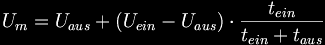
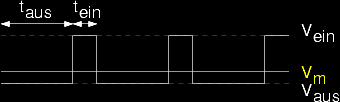
Varying the on- and off-switch-time of a rectangular signal with fixed base frequency, is described as Pulse Width Modulation [short: PWM]. The ratio ton / (ton + toff) is called duty cycle. Easy to perceive, what applies for the average value of the voltage:
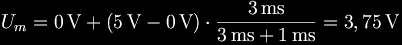
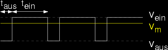
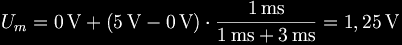
Uoff is usually 0V, Uon is the operating voltage, for instance 5V. ExamplesThe following examples are showing PWM-signals with a duty cycle of 75% resp. 25%.
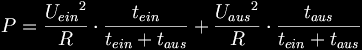
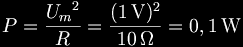
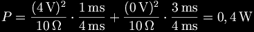
WattageIf you send a pulse-width-modulated signal directly to an ohmic consumer (i.e. hot-wire), you have to pay attention to the calculation of the wattage. Don't try: Instead you have to consider the wattage while on- and off-switching seperately:
Use as DA-converterIf you average the voltage with a low pass filter, you can use the pulse width modulation to generate analog signals (digital-analog-converter). Because the PWM-signal only consists of two different voltages, sometimes it is also called 1-Bit-DA-converter, but this term is actually misleading, for it has nothing to do with the solution of the resulting analog signal. The filter could be realised through a simple passive RC-combination for instance. It eliminates the high PWM base frequency and leaves over the analog signal. The critical frequency must be chosen in the way that the desired analog signal doesn't change. At the same time it has to be as low as possible to remove the upper waves of the PWM base frequency. A filter is not neccessary to control a DC-motor, the signal can directly be sent to the [Motortreiber]. The inertia of the magnetic field inside the motor is smoothing the signal sufficiently. Pulse width modulation is also used for generation of several output voltages of adjusters. Therefor a transistor with variable duty cycle will be controlled and by that the output voltage will be regulated. -- SaschaLudwig - 21 Jun 2004 -- KatharinaMueller (translation) - 24 Jun 2004 |
 .
.


 .
.


 .
.
 .
.
 .
.
|
|