
|
powered by:
![[Powered by Eventphone]](/pub/Main/BlinkenAreaLinkMenu/eventphone-logo.gif)
|
|
|
|
GroggyClock
|
 |
- coming soon -
The (provisional) name of this project leans on the original clocks from Gorgy-Timing.
Photos:
Finally I managed to take some photos of the test-boards and the clock. They can be found here: http://photo.astrastudio.de/v/GroggyClock/
history:
- 13.04.04 ordered missing components at Reichelt & Pollin
- 14.04.04 first tries decoding DCF77 with a PiC16F84
- 15.04.04 PiC16F84 decodes the DCF77 signal perfectly. Improved the program for output in shift registers, waiting for delivery from Reichelt & Pollin, built in negative 5V and LED signal for DCF77 clock pulse
- 16.04.04 Pollin & Reichelt delivered the ordered components. The blue LEDs are VERY bright! I have to dim them for certain. I bought a 4mm thick 50 x 50 cm clear sheet made of Polystyrol. Then I cutted the sheet in the size of 32,5 x 32,5 cm and drilled the holes for the LEDs. Sprayed black varnish on the back of the sheet and built in the LEDs, stuck and soldered them in.
- 17.04.04 Had a lie-in, soldered the flat cable onto each LED-pin. I drew the first draft of the circuit diagram.
- 18.04.04 Soldered test-board for shift register and hooked up some LEDs. Made various changes in the program to get rid of some mistakes.
- 19.04.04 minor changes in the program: LED display for the seconds implementated and sychronised with DCF pulse, time is now also running without further DCF pulse
- 20.04.04 improved circuit diagram
- 22.04.04 troubleshooting in DCF77 codeblock, because displays were only showing 00:00. After 20 minutes searching and testing, everything was running again. Built in output for 7-segmentation-display in the programm code. Connected testboard with 1 x 7-segmentation-display and watched the minutes counting up :-)
- 23.04.04 made testboard layout for the 4 x 7-segmentation-display, etched, drilled and equiped it
- 25.04.04 start running testboard. Is working very well :-). Made layout for an additional testboard for the seconds-LEDs, which I etched and drilled.
- 27.04.04 tidy up workroom, because nothing fits on the table anymore :-)
- 29.04.04 internal DCF77 antenna is working now
- 04.05.04 wrote test programm for RS232 interface and tested it
- 07.05.04 put software for RS232 interface into the clock and adjusted it
- 09.05.04 built and equiped second test board for controlling the clock, hooked up LEDs and tested it
- 14.05.04 searched for the bug at the second test board and soldered again the cold joints
- 15.05.04 adjusted PIC Code to the new microprocessor PiC18F242
- 16.05.04 made preparations for new board layout, it will have a size of around 30 x 30 cm, so that LEDs can be directly soldered on the board without tiresome connecting cables
- 19.06.04 long ago since writing last time...I admit...
In the meanwhile the CbC2004 took place, where I debugged the new PIC together with StefanSchuermans.
We had some really strange reactions of the PIC, among others the PIC caused a big internal short circuit after some time or after diverse measurements, so 2 PICs went up in flames.
2nd problem was: The clock rebootet after a minute or hang-up. I think, I found the reason of this problem, it seems to be my lab power adaptor. It can't smooth the voltage fluctuation properly, which results from the varying loading of the blue second-LEDs. This set the PIC into a strange condition, where it either rebooted, caused a short circuit and/or got blazing hot.
- 20.06.04 I developed brightness control for the LEDs with LDR & PwM. Used seperate PwM outputs for each color, so that blue and orange LEDs will have the same brightness.
planned features:
- time 0-24 hours, 0-59 minutes, 60 seconds

- DCF77 synchronized
- integrated DCF77 antenna + decoder
- impulse input 5-30 Volt (for extern DCF antenna)

- stopwatch
- countdown in any way
- RS232 interface
- DCF77 impulse output for additional clocks
- dimmer for LEDs
- time-aktive relay output
- alarmclock
- internal/external temp sensor with output via RS232 & display
That's how it will look like:
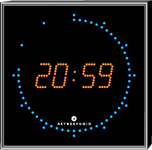
Because of good readability and these are simply the original colors - now in red, as it hangs in every studio:
Thanks to StefanSchuermans for his brilliant ideas and the first rough circuit diagram.
-- SaschaLudwig - 20 Jun 2004
-- KatharinaMueller (translation) - 24 Jun 2004
|
|